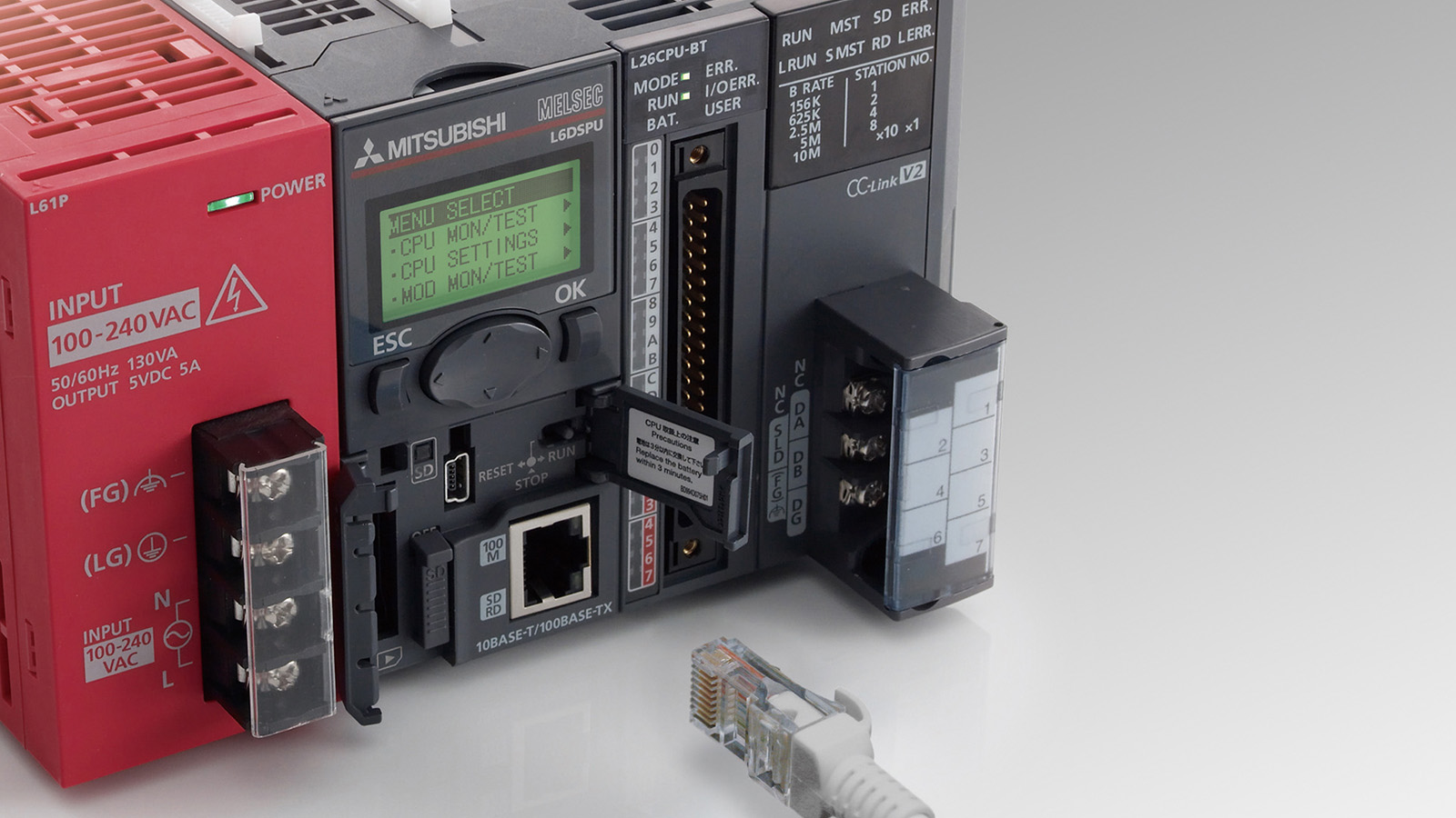
What is a PLC?
PLC is an abbreviation consisting of the initials of the words "programmable logic controller" (Turkish: programmable logic controller). It is the name given to a special computer used for electromechanical control of machines such as robots, conveyor belts, pneumatic equipment, etc. that make up the production lines in factories. They have input and output connections just like the Arduino microcontroller cards we use in our projects. In this way, it is responsible for reading data from various sensors, controlling various output units (actuators such as motor drives, solenoid valves, etc.) according to the program scenario created, and providing communication with other input / output and monitoring (SCADA) units.
The biggest difference between PLCs and microcontroller boards as we know them is that they are designed to operate in much more severe physical conditions (high or low temperature, dust and humidity, mechanical vibration and impact, electronic interference and noise, etc.) while maintaining their stability.
How Does PLC Work? Where is it Used?
PLCs are used logically by programming them just like Arduino, PIC etc. microcontrollers. We control the function we want the PLC to perform, for example the control of a motor drive, by creating programs to change the inputs and outputs on it. Most microcontrollers today use an input/output voltage of 3.3V or 5V. In PLCs, this voltage is 24V.
PLCs contain components such as a processor, RAM and ROM memories required for storing and running programs, input/output modules, communication modules, just like our computers. The most important feature of the PLC is that the program commands are processed in real time and sent to the modules connected to the outside world such as input/output and communication modules in the shortest possible time. Thus, they can be used in industrial applications where timing is critical.
The operating logic of a PLC is as follows: Inputs are read and their logic values (1 or 0) at the time of reading are stored in memory. These inputs are interpreted according to the program written. Necessary communication operations are performed and the programmed outputs are set to be logic 1 or 0 (expressed in 24V or 0V). As I mentioned in the paragraph above, this process takes place in a very short time (in milliseconds).


